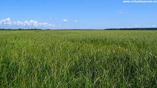
When creating a 3D scene that represents a natural landscape, we want it to be pleasant to look at (at least, in most cases ;D). That’s why you have to consider greenery and especially grass!
One of its particularities is that it grows in very large numbers on more or less large surfaces. The real challenge, when modelling it, is to be able to generate as few polygons as possible on the screen, which is not a simple task. It is therefore imperative to think early on about space and computation optimisation so that the result is compatible with real time.
There are different approaches to realise a grass. In this article we will see how to model grass blades using billboards and how to optimise it via LOD. Of course this method is not perfect and can be improved but it produces an interesting result.
Getting started
As we want to optimise as much as possible, we will consider our clump of grass as a particle. Generally, particles in computer graphics are processed by the GPU which will draw the polygons while the CPU will only manage the positions at the base of the particle. To achieve this, we will focus on writing shaders which are programs used by the GPU to display objects on the screen.
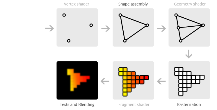
We will therefore generate points for the base of our blades of grass. We can make a grid or adapt it to the surface of the terrain. In this article, we will make a list of points in a grid and then send them to the GPU. Each point will be processed by the vertex shader and the result will then be sent automatically by the graphics card to the geometry shader. It is the geometry shader that will have the role of actually creating our tufts. Then these shapes will be sent by the graphics card to the fragment shader so that we can calculate the right colour for each pixel. Between each shader mentioned above, there are others but we will not use them.
I suggest a small codebase that displays points (for positions at the base of the particles) on the screen: GitHub: grass-tutorial_codebase.
If you’re not familiar with OpenGL, I highly recommend the learnopengl tutorials to get started.
In the rest of the article, we will mainly modify the grass.vs, grass.gs and grass.fs files, which correspond to the vertex, geometry and fragment shader respectively.
Under Linux, after unpacking the file, you can compile the program as follows from the /grass-tutorial_codebase folder:
mkdir build
cd build
cmake -DCMAKE_BUILD_TYPE=Release ..
make
./program
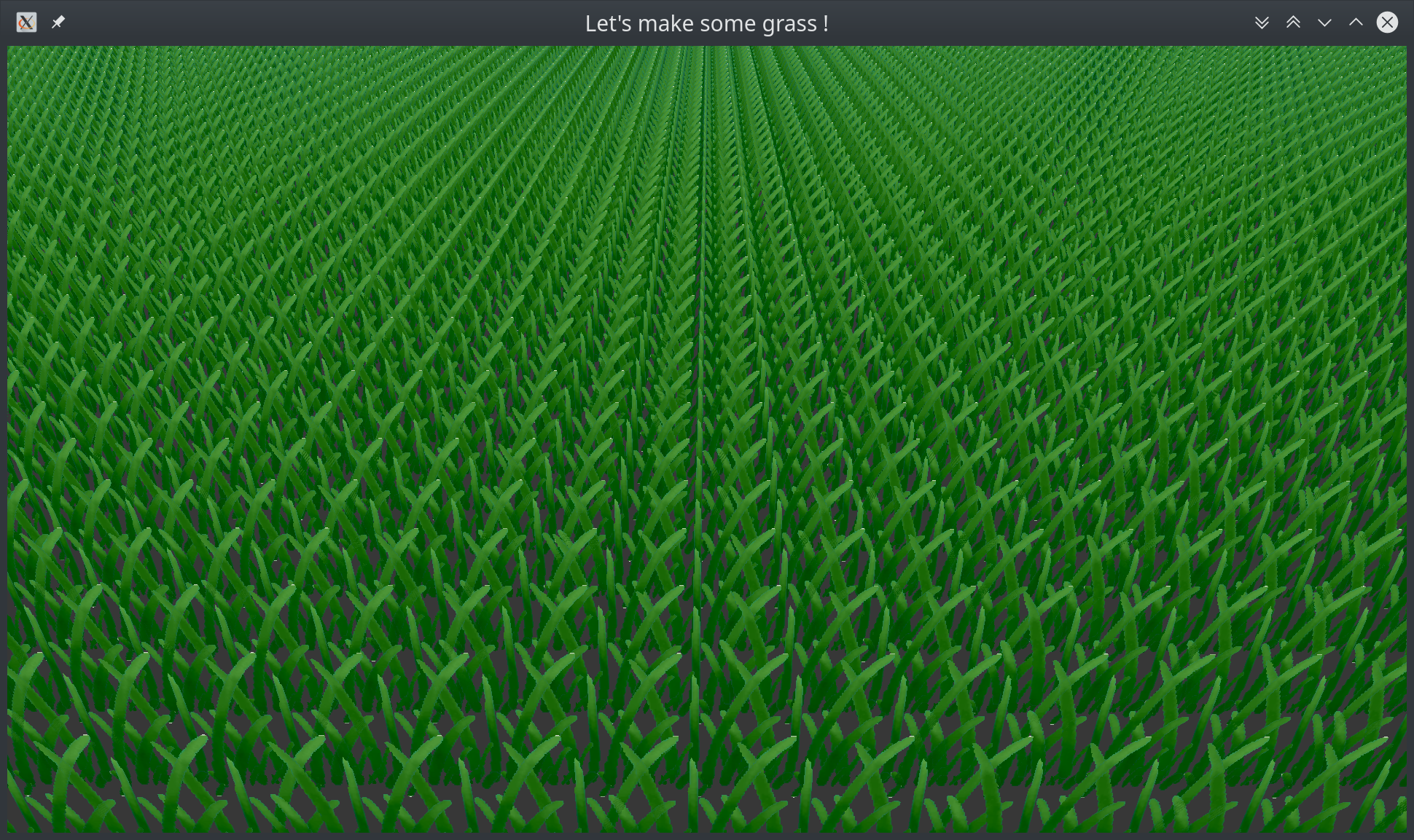
If all goes well, you should have a result that looks like this:
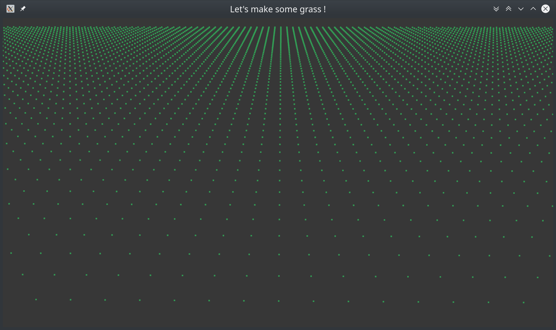
Here we go!
As explained above, we will use billboards. This is a 2D image that we will place in our 3D environment, giving it an impression of volume. This technique allows us to gain in efficiency by reducing the number of polygons displayed on the screen and we will therefore be better able to process a large quantity of herbs at the same time. In addition, this image very often represents a clump of grass and not just a simple blade. Here again, the number of polygons will be increased as opposed to representing each blade one by one. Unfortunately, this method has the drawback of not being very realistic and to overcome this problem, we will have to “cheat” to make the rendering more natural.
Step 1. Create a simple quad.
Let’s start by creating a rectangle. The positions of the particle base are created and sent as points to the graphics card using OpenGL’s GL_POINTS command in the main.cpp file. In this way we will create one rectangle per position.
Vertex shader
In the vertex shader grass.vs, we will be careful not to multiply the position of the points by the view and projection matrices as we want to keep the positions in the world frame. Thus, when we create our billboards, they will be in the world frame and only after we have created the coordinates of the quad will we be able to project them into the screen frame.
gl_Position = vec4(aPos, 1.0);
Geometry shader
The idea is that we take our base position and add points relative to the base to form a quad. These points are often called offset points.

We will create a function createQuad in the grass.gs which will take as an argument the base position of our particle and thus of our quad that we will create.
We will then use an array of 4 values corresponding to the coordinates of the offset points relative to the base position. These values can obviously vary and I invite you to test different coordinates.
vec4 vertexPosition[4];
vertexPosition[0] = vec4(-0.2, 0.0, 0.0, 0.0); 	// down left
vertexPosition[1] = vec4( 0.2, 0.0, 0.0, 0.0);  // down right
vertexPosition[2] = vec4(-0.2, 0.2, 0.0, 0.0);	// up left
vertexPosition[3] = vec4( 0.2, 0.2, 0.0, 0.0);  // up right
We will then do a for loop to iterate on this array. This is when we will create our vertex. Don’t forget to multiply by the view and projection matrices!
for(int i = 0; i < 4; i++) {
	gl_Position = u_projection * u_view *
				 (base_position + vertexPosition[i]);
	EmitVertex();
}
EndPrimitive();
layout (triangle_strip, max_vertices = 4) out;You can find all the code by clicking on grass.gs. Normally, you will see a green extension in your window when you launch the application.
Fragment shader
The fragment shader here just gives the same colour for each rectangle we create. Of course, we’ll be adding to this shader as we go along to make it fit our needs.
Step 2. Applying a texture
Well, it’s not very interesting to have green rectangles so let’s add a texture to our quads. The idea is to put a texture on our quads to display our grass field.
We’re going to have to modify the main.cpp file. Fortunately, in the given code base, you have access to a library called stb_image which will allow us to retrieve the image information.
Before the rendering loop, we will load our image using the loadTextureFromFile function. This function, already defined at the end of the main.cpp file, renders the texture index to us directly. We then need to tell the shader that this is the first texture we are going to use.
unsigned int texture1 =
	loadTextureFromFile("../assets/textures/grass_texture.png");
glUseProgram(shaderID);
glUniform1i(glGetUniformLocation(shaderID, "u_textgrass"), 0);
Then, in the rendering loop before the ``glDrawArrays’’ part, we need to tell OpenGL that we are activating the first texture and that it is of index texture1.
// bind textures
glActiveTexture(GL_TEXTURE0);
glBindTexture(GL_TEXTURE_2D, texture1);
So we will have to indicate the texture coordinates on our quad in the geometry shader. Just as we did with the offset positions, we will create an array of size four to indicate the texture coordinates for each point.
vec2 textCoords[4];
textCoords[0] = vec2(0.0, 0.0); // down left
textCoords[1] = vec2(1.0, 0.0); // down right
textCoords[2] = vec2(0.0, 1.0); // up left
textCoords[3] = vec2(1.0, 1.0); // up right
We’ll need to add a vec2 textCoord variable which we’ll send to the fragment shader via the GS_OUT structure.
We also need to change the iteration loop so that it takes into account the texture coordinates according to the points we create.
for(int i = 0; i < 4; i++) {
	gl_Position = u_projection * u_view *
				  (base_position + vertexPosition[i]);
	gs_out.textCoord = textCoords[i];
	EmitVertex();
}
EndPrimitive();
In the fragment shader, we then need to add vec2 textCoord to the FS_IN structure. Don’t forget to add our new uniform corresponding to the texture we are using.
uniform sampler2D u_textgrass;
We can now retrieve the pixel on the texture at the texture coordinates that have been specified by the geometry shader and interpolated by the GPU.
void main(){
	vec4 color = texture(u_textgrass, fs_in.textCoord);
	if (color.a < 0.05 ) discard;
	FragColor = color;
}
if (color.a < 0.05 ) discard;If all goes well, you should have a result that looks like this:
Step 3. Modifications that add realism
Cross arrangement of quads.

We want to represent a clump of herbs that is filled in. So to add this effect of volume, we will draw two other quads which we will arrange crosswise.
To do this, we can add a createGrass function which will call the createQuad function three times.
// create a cross grass
void createGrass()
{
	mat4 model0, model45, modelm45;
	model0 = mat4(1.0f);
	model45 = rotationY(radians(45));
	modelm45 = rotationY(-radians(45));

	createQuad(gl_in[0].gl_Position.xyz, model0);
	createQuad(gl_in[0].gl_Position.xyz, model45);
	createQuad(gl_in[0].gl_Position.xyz, modelm45);
}
You will have to change the arguments of createQuad by adding a mat4 crossmodel matrix as a parameter to the function. Don’t forget to multiply the position of the point with the crossmodel matrix as follows:
gl_Position = u_projection * u_view * (gl_in[0].gl_Position
		+ crossmodel * vertexPosition[i]);
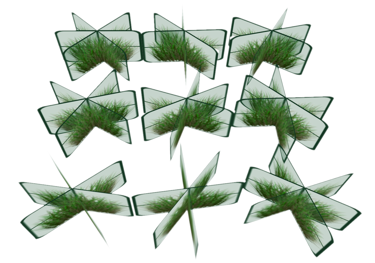
In main, you now just call the createGrass function. If all goes well, you should get a result similar to the screenshot below.

Rotation aléatoire sur Y
Our grass blades have more volume but it doesn’t look natural. To improve the visual and display a more realistic rendering, we will rotate each grass cross into a random value on the Y axis.
To do this we will need rotation operations, you can grab functions here.
We also need a random function. In GLSL, there is no such thing as a random value. So we are forced to “cheat” by simulating randomness by doing operations that will create a number based on the maximum values of the GLSL types.
const float PI = 3.141592653589793;
...
createQuad(vec3 base_position, mat4 crossmodel){
	...
	mat4 modelRandY = rotationY(random(base_position.zx)*PI);
	...
	gl_Position = u_projection * u_view * (gl_in[0].gl_Position +
            	modelRandY*crossmodel*vertexPosition[i]);
}
rotationX, rotationY and rotationZ take angles in radians as parameters. This is why you need to multiply by PI to make the result consistent.You should get the following result:
Random size of grass tufts

Depending on where the grass is, it will not grow in the same way and at the same speed. We could use a noise function to give it a random size, but for simplicity we will use the float random (vec2 st) function.
In the main vertex shader, we will create a grass_size variable to which we will assign the value :
float grass_size;
const float c_min_size = 0.4f;
...
void main() {
    ...
    grass_size = random(gl_in[0].gl_Position.xz) * (1.0f - c_min_size)
    		+ c_min_size;
    ...
}
Here we assign a random value to the grass clump by multiplying it by a random number (between 0 and 1) on the maximum size of the plant. Then we add the minimum size we want.
Then in the createQuad function, multiply vertexPosition[i] with grass_size.
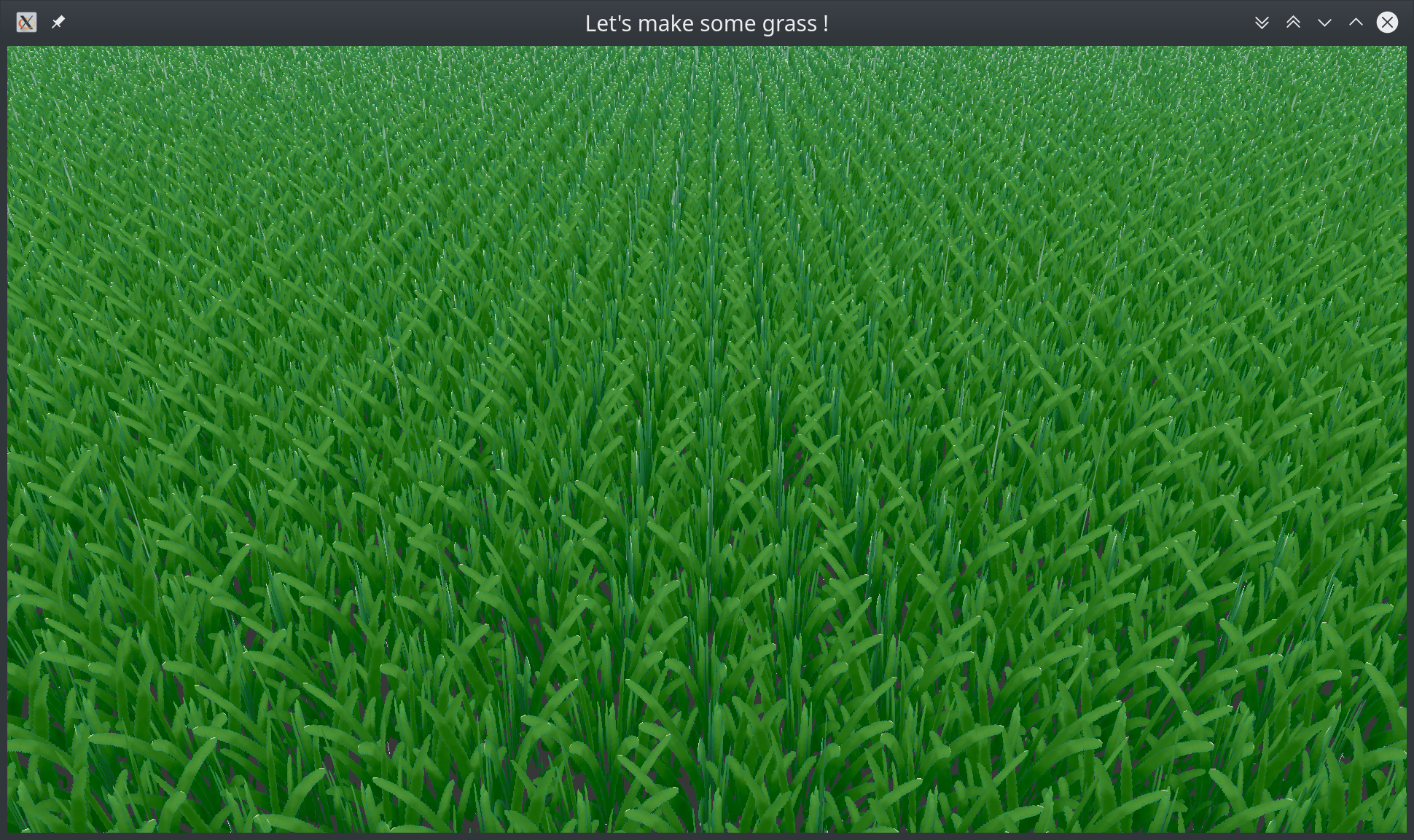
Now you should get a better result!

Working with colours
Just as we changed the size of the grass in a random way, we can create a variation of colours. To do this, we will use the fbm function corresponding to Fractal Brownian Motion which corresponds to a noise with variable amplitudes.
We will transfer a float to the fragment shader thanks to the gs_out structure by assigning its value in createGrass
gs_out.colorVariation = fbm(gl_in[0].gl_Position.xz);
Then in the fragment shader, we apply the value of the variation by mixing the texture colour with its darker version before passing the colour into FragColor.
color.xyz = mix(color.xyz, 0.5*color.xyz, fs_in.colorVariation);
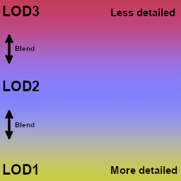
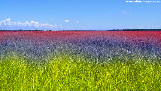
Level of Detail (LOD)
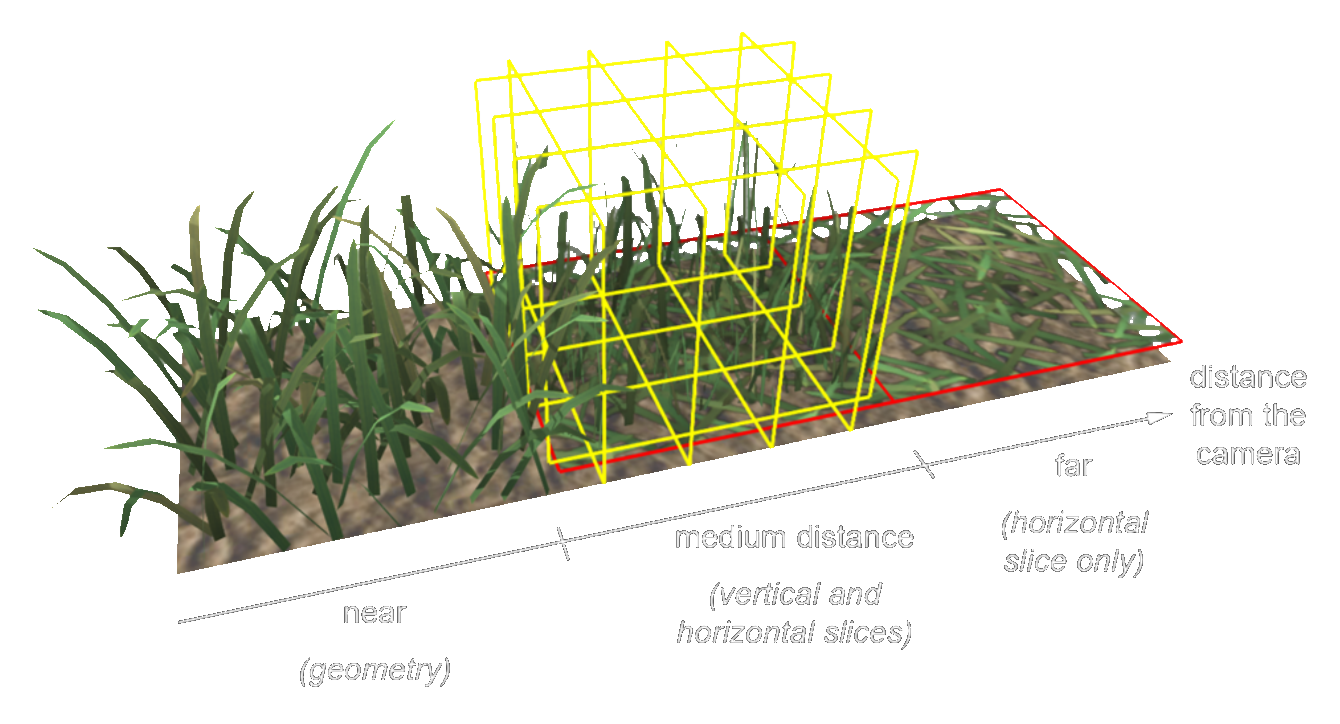
Objects displayed far from the camera do not need to be as detailed as those displayed close to the camera. Therefore, the number of polygons on the screen can be saved dynamically in relation to the distance to the camera.
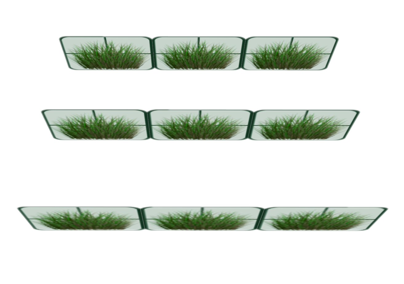
The idea is to keep as much precision as possible for the clumps of grass that are close. We will therefore draw them with three quads and the further away they are, the more quads we will remove from them.
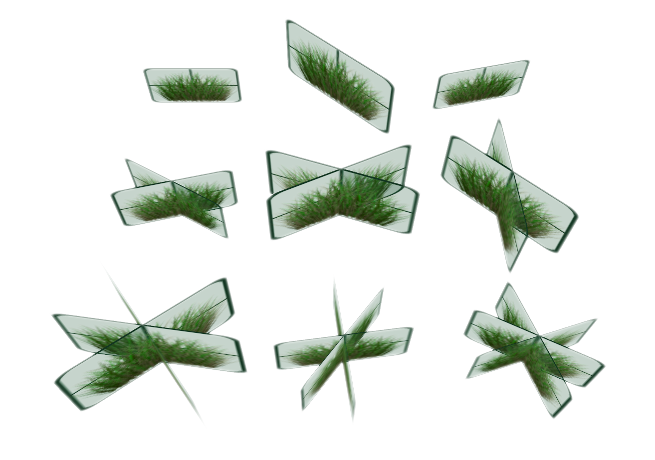
If this is done correctly, you should not notice any difference from the previous result.
As can be seen in the photograph, to achieve the best possible LOD, it will be necessary to create transition zones between the different levels of LOD.
To do this, we will need to modify the createGrass function so that it takes as a parameter the number of quads we wish to draw.
switch(numberQuads) {
	case 1:	{ // low LOD
		createQuad(gl_in[0].gl_Position.xyz, model0);
		break;
	}
	case 2:	{ // medium LOD
		createQuad(gl_in[0].gl_Position.xyz, model45);
		createQuad(gl_in[0].gl_Position.xyz, modelm45);
		break;
	}
	case 3:	{ // Hight LOD
		createQuad(gl_in[0].gl_Position.xyz, model0);
		createQuad(gl_in[0].gl_Position.xyz, model45);
		createQuad(gl_in[0].gl_Position.xyz, modelm45);
		break;
	}
}
So in the main of the geometry shader, we must now take into account the LOD, for this we will have to define the thresholds of the LOD. That is to say, we will have to say at what distance we will go from one LOD level to another.
const float LOD1 = 5.0f;
const float LOD2 = 10.0f;
const float LOD3 = 20.0f;
...
void main(){
	vec3 distance_with_camera = gl_in[0].gl_Position.xyz
					- u_cameraPosition;
	// distance with camera position
	float dist_length = length(distance_with_camera);
	// random tuft size
	grass_size = random(gl_in[0].gl_Position.xz) * (1.0f - c_min_size)
			+ c_min_size;
	// creating quad depending of the camera's distance
	if (dist_length < LOD1) { createGrass(3); }
	if (dist_length >= LOD1 && dist_length < LOD2){ createGrass(2); }
	if (dist_length >= LOD2 && dist_length < LOD3){ createGrass(1); }
}
But this naive method does not give a good result. Indeed, one can clearly see a transition between each LOD level. And let’s face it, it stings the eyes! :D
So let’s think of another way to do it. We will have to manage a transition zone and allow some of the grass clumps to be located at a LOD level where they should not have been initially.
// distance of the camera's position with transition
float t = 6.0f; if (dist_length > LOD2) t *= 1.5f;
dist_length += (random(gl_in[0].gl_Position.xz)*t - t/2.0f);

// change depending of the distance
int lessDetails = 3;
if (dist_length > LOD1) lessDetails = 2;
if (dist_length > LOD2) lessDetails = 1;
if (dist_length > LOD3) lessDetails = 0;

// create grass
if (lessDetails != 1
  || (lessDetails == 1 && (int(gl_in[0].gl_Position.x * 10) % 1) == 0
  || (int(gl_in[0].gl_Position.z * 10) % 1) == 0)
  || (lessDetails == 2 && (int(gl_in[0].gl_Position.x * 5) % 1) == 0
  || (int(gl_in[0].gl_Position.z * 5) % 1) == 0)
)
{ createGrass(lessDetails); }
Now if the camera moves, the change in LOD levels is not very noticeable. Of course, this effect can be improved by adding more conditions for the changes between levels.
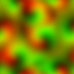
Wind animation
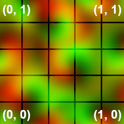
The grass is nice with its LOD but it remains static. Let’s add wind animation. We could use a mathematical formula to model its movement but it may be simpler to use a flow texture. This texture differs by its values. Indeed in our flow texture, the red value of the image represents the direction in x, the green value of the image corresponds to the direction y and sometimes, in some of these textures, there is a blue value which encodes the force of the wind.
We will take a texture that has both red and green values (i.e. the wind direction). As our image will repeat like a mozaic on our terrain, we can use the coordinates of the quads as texture coordinates.
By calculating the matrix that will tilt our quad in the createQuad function after the declaration of the texture array, we can calculate the tilts as follows:
vec2 windDirection = vec2(1.0, 1.0);
float windStrength = 0.15f;
// texture coordinates of the moving wind
vec2 uv = base_position.xz/10.0 + windDirection * windStrength * u_time ;
uv.x = mod(uv.x,1.0);
uv.y = mod(uv.y,1.0);

vec4 wind = texture(u_wind, uv);
// we calculate the matrix that allows the quad to be tilted according to the
// wind direction and force
mat4 modelWind =  (rotationX(wind.x*PI*0.75f - PI*0.25f) *
		  	rotationZ(wind.y*PI*0.75f - PI*0.25f));
Then, in the iteration loop, we will apply this wind model matrix to the top corners of our quads. This way, the base of the grass will not move and it will give a natural feel to the wind.
mat4 modelWindApply = mat4(1);
// for each quad's corner
for(int i = 0; i < 4; i++) {
	// to apply the wind only to the top corners
	if (i == 2 ) modelWindApply = modelWind;
	// compute final position
	gl_Position = u_projection * u_view *
        (gl_in[0].gl_Position + modelWindApply*modelRandY*crossmodel*
        			(vertexPosition[i]*grass_size));

	gs_out.textCoord = textCoords[i];
	EmitVertex();
}
EndPrimitive();
The source code is available on GitHub : grass-tutorial_finalcode.
Possible improvements
It is possible to improve the rendering by adding a grass layer drawn twig by twig in the geometry shader for the first level of LOD. In the second level, we could put billboards like in this tutorial. Then for the last level, we would only put a texture on the terrain. This method was proposed during the thesis defense of Kévin Boulanger and presented at Siggraph 2006.
Also, one might want to add other textures without impacting the performance of the render. To do this, it would be easier to set up an atlas of textures.
 3D voxelic engine